For quite a while now, the tech world has been smitten with the Raspberry Pi. Since it came on the scene in 2012, it’s evolution and innovation has remained widely successful when it comes to the automation of tasks. From emulating video games, to automating private homes, to even hacking various electronics, the Raspberry Pi proves itself a dominating force in automation. So of course the next natural step is integrating it in the industrial automation sector.
Of course there exists questions regarding implementing Raspberry Pi into automation. “How would it be used?” “Why would anyone use it?” “What advantages does it have?” In this article we will explore the capabilities of the tiny but mighty process board and what about it and its potential in the industrial sector.
Raspberry Pi: A Brief Introduction
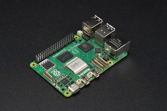
If you’re in the tech sector for whatever reason, be it profession or hobby, chances are you have encountered the Raspberry Pi at some point. At the very least you may have heard of it. For those who don’t know, the Raspberry Pi is commonly designated as a SBC or Single-Board Computer. Honestly, this characterization is pretty accurate. The main computer component of the Pi is the size of a credit card, with the enclosure, you’re looking at a device that is about the size of a pack of cigarettes.
So a small pocket-sized computer is cool, but what does it do? Well, surprisingly a lot of things! Hobbyists use the Pi when working with things such as robotics. Instructors find Pi as an easy way to teach programming languages to students. For the longest time Pi has gained prominence amongst private consumers and institutions.
However, most recently, Pi has proven itself very useful in the industrial sector as well.
The Beginning of Raspberry Pi
Raspberry Pi’s origins traces back to Cambridge University during the early 2000’s. A group of engineers headed by Eben Upton sought ways to rekindle interests in programming among a younger generation. Today, sites like CodeMonkey, have enough demand from children as young as five years old wanting to get into programming. However, in the early 2000’s programming remained a niche interest that required sophisticated knowledge of computational language to do. It existed as a far cry from the more streamlined process that we see today.
In 2006 Upton and his team set out to design a small computer no bigger than a credit card, that was widely programmable, affordable, and adaptable in running various programs. Their work finally came to fruition in 2012 with the release of the Raspberry Pi Model B. Features on this tiny triumph included both USB and HDMI ports. It also sported a SD card slot for storage capabilities. Best of all it was all packaged at a price point of $35. This made it an overnight hit with professionals, educators, and hobbyists alike.
Integrating Raspberry Pi Into Industrial Automation
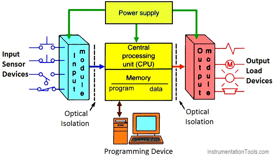
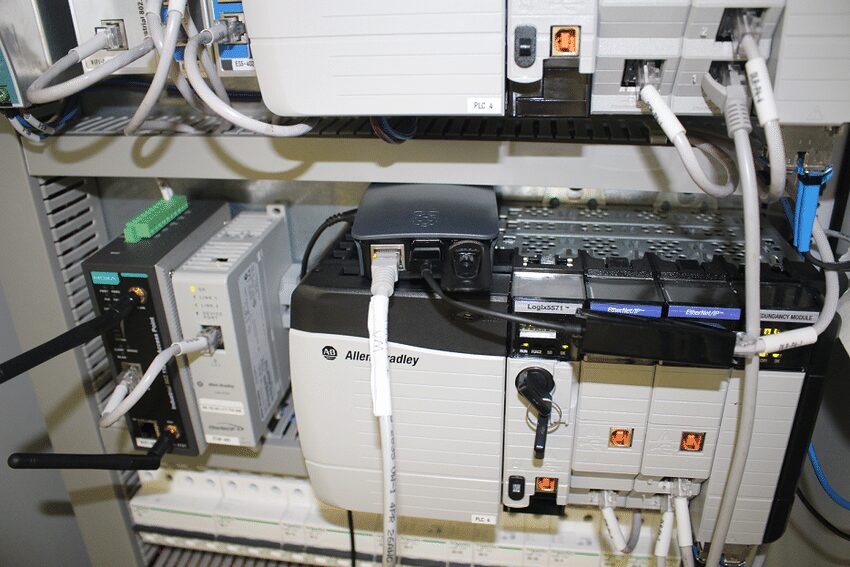
So how did this unassuming little single-board computer get the attention of the automation industry? For starters, it’s a very affordable platform that can complete a multitude of tasks. Additionally the small size of Pi also lends to them being energy efficient. In the industrial sector, Pi boards can be integrated into sensors and used in server units. They can be used to help manage and control PLCs. Some independent developers have coded apps that allow a Pi board to be used as a PLC.
Arguably, the largest advantage Pi has in the industry is that it exists as a platform that is not tied to any one manufacturer and can be integrated with a wide variety of equipment. You don’t have to worry about whether it’s compatible with Schneider or Yaskawa.
Interested in PLCs
MRO Electric has a number of PLCs in stock available. Access the catalog here. For more information a sales representative can be reached through email: sales@mroelectric.com or by phone: (800) 691-8511. We also offer repair services.