In industrial automation, the significance role contactors play gets overlooked. These unassuming yet pivotal components orchestrate the machinery and processes within manufacturing worldwide. From controlling motors to managing power distribution, contactors play a fundamental role in ensuring seamless operations across various industrial sectors.
Read more: The Role of ContactorsWhat is a Contactor?
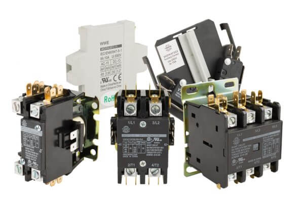
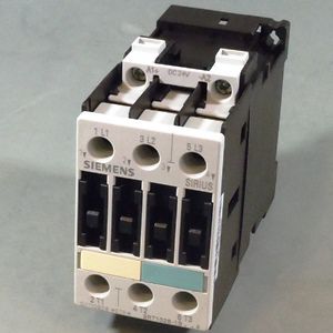
At its core, a contactor exists as an electromechanical switch designed to control an electrical circuit. Unlike conventional switches, which operate manually, contactors primarily become utilized in scenarios where automated control is essential. They consist of a coil, which when energized, generates a magnetic field. This field attracts a movable armature, causing electrical contacts to close or open.
Contactor Applications in Industrial Automation
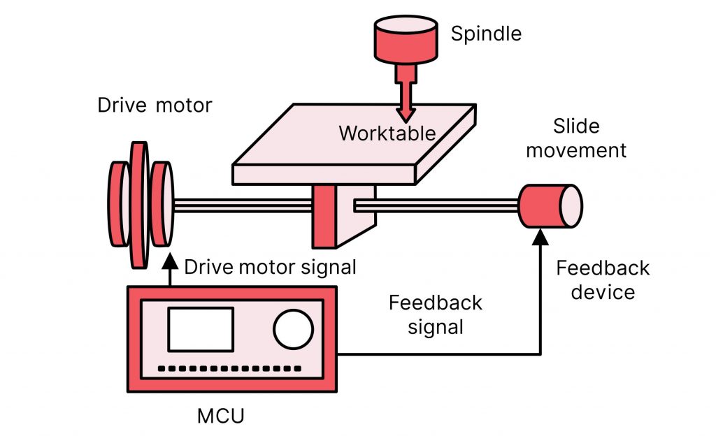
- Motor Control: Contactors find extensive use in motor control applications. In industrial settings, contactors serve as the gateway for starting, stopping, and reversing motor operations. By effectively managing the flow of electrical power, contactors ensure smooth and precise control over motor functions. This contributes to enhanced productivity and safety.
- Power Distribution: Efficient power distribution is critical for maintaining operational integrity within industrial facilities. Contactors facilitate this by enabling the selective routing of electrical power to different equipment and processes. Acting as switches for high-power circuits, contactors ensure power being directed only where and when needed. This optimizes energy utilization and minimizing wastage.
- Heating and Lighting Control: Contactors also play a vital role in managing heating and lighting systems within industrial environments. They regulate the supply of electricity to heaters, lighting fixtures, and other auxiliary devices. Ultimately, contactors contribute to creating optimal working conditions while simultaneously conserving energy and reducing operational costs.
Advantages of Contactors in Automation
- Reliability: Companies build contactors to withstand the rigors of industrial environments, ensuring dependable performance even under challenging conditions.
- Scalability: Whether controlling a single motor or orchestrating complex automation networks, contactors offer scalability, making them suitable for diverse industrial applications.
- Safety: With features such as overload protection and arc suppression, contactors enhance operational safety by mitigating the risk of electrical faults and hazards.
- Remote Control: Advanced contactor systems are integrable into broader automation frameworks, allowing for remote monitoring and control of industrial processes. This greatly improves operational efficiency and responsiveness.
Challenges and Innovations
While contactors have long been integral to industrial automation, ongoing advancements in technology continue to shape their evolution. Miniaturization, enhanced efficiency, and integration with digital control systems are just some of the areas witnessing innovation within the realm of contactor functionality. Moreover, the advent of predictive maintenance techniques empowered by artificial intelligence promises to further optimize the reliability and performance of contactor systems, minimizing downtime and maximizing productivity.
In Need of Contactors?
.MRO Electric offers a variety of contactors well-suited for your automation needs. For more information on contactors send an email to sales@mroelectric.com or call (800) 691-8511. Read more information on components of industrial automation equipment, here.
Conclusion
From motor control to power distribution, their versatility and reliability make them indispensable assets across a spectrum of industrial applications. As technology marches forward, the evolution of contactors continues, poised to further elevate the efficiency, safety, and scalability of automated systems in the years to come.